
This article is…
The content of this course is a step-by-step explanation of how to use the tools and tricks often used in Blender modeling while creating 3D models.
If you want to learn how to use 3DCG software, I recommend that you learn while creating 3D models.
If you decide on the 3D model you want to make and work your way through this article, you’ll be able to do at least some modeling in Blender anyway!
I wrote this article aiming for such content, and it turned out to be very long.
If there is something you want to pinpoint, we have prepared a Dictionary-like index of item-by-item summaries, so you can find the item you want to know about from there.

Also, Blender Modeling [Knowledge] If there is a supplemental explanation in another article in the blog, such as, the text is a link to the article. Please check the links as necessary~.
*The position of the link may be shifted when displaying the content of the link on a smartphone or other device.
- Decide on the model you want to create just right
- Actual modeling (1) Up to symmetrical preparation with mirrors
- Actual modeling (2) Editing polygons and vertices in various ways
- Actual modeling (3) Fine tuning and Finishing
- Summary: When the model is completed, the modeling operation is approximately known
Decide on the model you want to create just right
When learning how to use a new 3DCG software, it is recommended that you learn how to use it while creating the model you want to make, in Toha’s opinion.
There are 3 reasons why we recommend it.
- Priority is given to learning how to use functions that are used frequently.
- It’s easy to memorize what you need to learn when you need to learn it.
- When the model is complete, we can do the minimum we need to do.
Although 3DCG software has many useful functions, it is possible to create 3D models without understanding all of the functions. Therefore, while creating the model you want to make, you should learn how to use the software.
I want to do something like this -> I’ll find out how -> I’ll try -> the model is also complete
If you follow this cycle, you can kill two birds with one stone by creating what you want to create while also learning what is necessary to create it.
Studying to “make what you want to make” also helps to maintain motivation.
I think it is more fun to make 3D models that you want to make than to make 3D models for tutorials that are not very interesting.
And when you learn how to use 3DCG software, you will have completed the 3D model you wanted to create.
When you think about it, it’s kind of motivating – isn’t it?
What is important here is how you decide on the 3D model you want to create.
When deciding on the 3D model you are going to make, there are a few points you should consider.
- Choose something you like, something you enjoy making, something you truly want to make.
- However, don’t choose something too complicated from the start.
- Find “just the right feeling” that is easy to make and keeps your interest.
- Make it something that can gather a lot of reference material from what is already in the world.
This may seem abstract and a bit confusing.
For example, even if you love Pokémon, you should not suddenly make a Charizard, but start with a Charmander.
If you think Charmander looks quite difficult, you can try making Poliwag the first one.
If it is Pokémon, many materials can be used as references, such as pictures, games, and stuffed animals.
When it comes to the original characters of your design, the hurdle is higher because you need to create your characters from reference materials.
If the task is too difficult or the hurdle to completion is too high, you will not be able to maintain your motivation until the end, and you are more likely to fail in the process of making it.
The trick is to choose a 3D model that looks fun to make that you feel you can somehow create yourself, and that has “just the right feel” to it while learning how to use the software.
*3D models of copyrighted works should be made for practice or fan art.
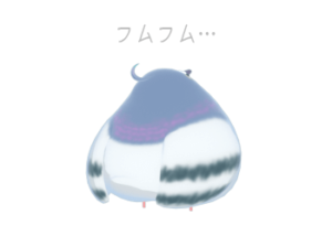
Incidentally, the model of Toha is the first 3D model I made in Blender.
- I wanted to create a 3D model to use as an icon for Toha himself.
- Not too complicated, not too difficult, just the right kind of design.
- I want to pose it so I can study the bones and weights.

Since this is an original model, there is not much material available, but I have prepared that area myself. (Reference: Materials I collected to create the Toha model )

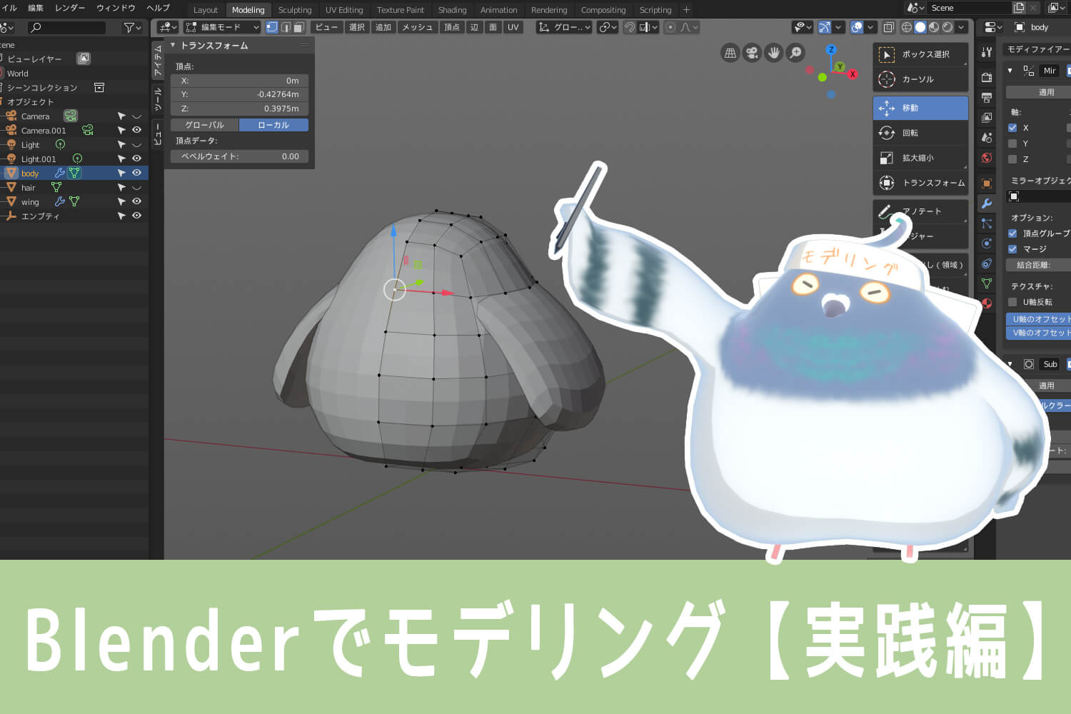
From now on, I would like to look at modeling in Blender while creating a Toha model as an example.
Actual modeling (1) Up to symmetrical preparation with mirrors

Now let’s get on with the modeling.
It is easier to create a 3D model of a character if the base part is modeled symmetrically. First, we will proceed to the preparation stage of symmetrical modeling.
When you start Blender, there is a cube object in the middle, but since we are going to delete the default cube with Delete, we will start by adding a cube object.
For more information on how to operate the 3D viewport, please see Blender Basic Operation Please refer to the explanation in How to Use Blender. In addition, we will basically model in a way that does not use shortcuts.
In fact, Blender’s extension: Auto Mirror allows you to complete what follows “from deleting half the object to applying the mirror modifier” with a single click of a button.
For more information on add-ons and shortcuts that are useful to use, see Modeling with Blender [addendum] article. If you want to use Blender more conveniently, please take a look~!
– Adding Objects
Add objects to your Blender scene.
Objects can be added from the You can do this from the header menu under [Add]. When you click [Add], you will see a menu like this.
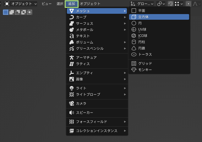
Basically, any object you want to add to your Blender scene can be created from this Add menu.
Meshes, curves, text, lights, cameras… the list goes on. Cylinders, spheres, torus (doughnut-shaped) objects, etc. can be added by selecting them from the Mesh section.
Now we want to add a cube object, so we choose Add->Mesh->Cube.
– Advanced settings in the Operator panel
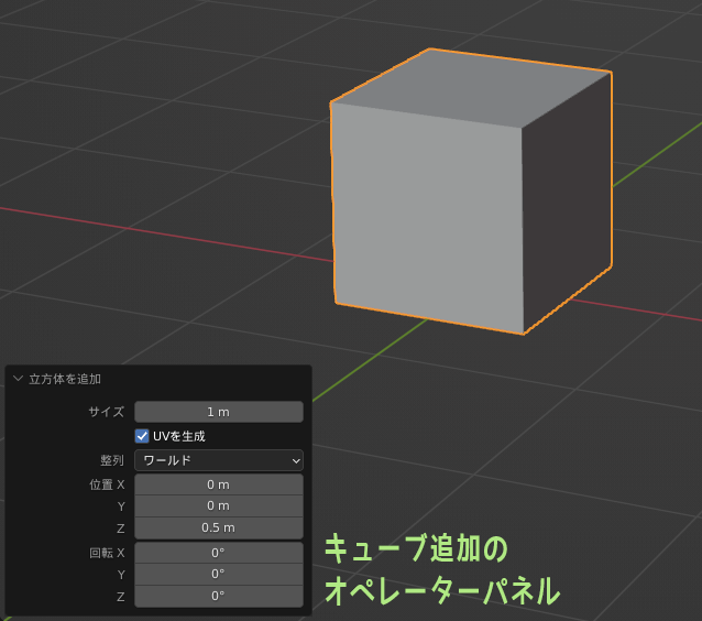
Once the cube is added, an Operator panel will appear.
If it appears small, click on it to enlarge the panel.
In the operator panel when adding a cube object, you can change the size and position of the cube. If you set the size to 1 m and the position to (0, 0, 0.5 m), you can create a cube that looks like this
– Blender’s standard unit of measure
Blender’s default reference unit is Meters (m).
For this reason, the units for cube size and location are in meters.
The base unit can also be changed.
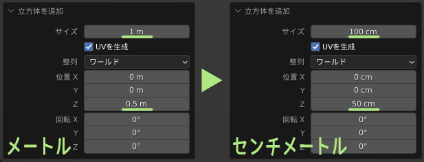
From the Property Editor Select the Scene tab and you will find a “Units” section. If you change the Length field from meters to centimeters, the base unit will change to centimeters (cm).
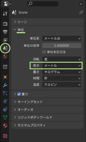
When the reference unit is set to centimeters, units in the operator panel will also change to centimeters.
Basically, Blender’s default unit settings should be fine, but when exchanging data with 3DCG software that uses a different standard unit, problems may occur due to the difference in units. (In Maya, the standard unit is centimeters.)
Since we just checked the units, you can proceed as you are with meters.
– Loop Cutting Tool
I want to cut the added cube in half in preparation for modeling it symmetrically.
First, select the cube, and if it is in object mode Edit Mode.
Then, from the Toolbar, loopcut.
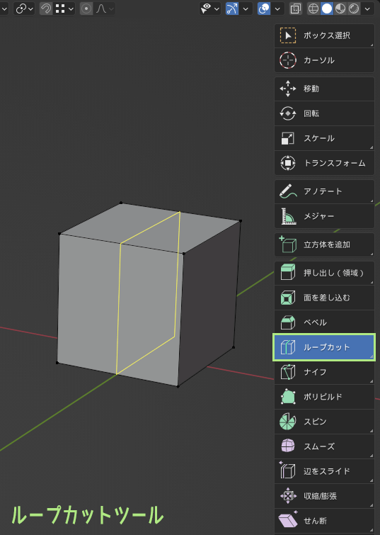
If the square polygons are connected, it will automatically cut around the area.
The cut is made through the midpoint of the edge, but operator panel to adjust the position of the cut and the number of divisions.
Personally, the loop cut is an easy-to-use tool that I use very often.
Since we are now only cutting the cube in half, we will not change any of the operator panel settings.
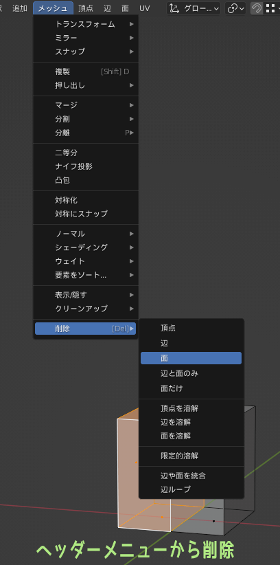
– Delete polygons
In preparation for symmetrical modeling, delete half of the polygons on the left side of the screen of the cut cube.
Surface Edit Mode to Select the polygon you want to delete. If you want to select the hidden backside, select Transparent display is turned on.
Select the polygon you want to delete and press Delete to display the Delete menu. If you want to delete the selected polygon normally, press Delete→Surface.
![Blender [Delete]キーでポリゴン削除](https://tohawork.com/wp-content/uploads/2022/09/b28_modeling_07.png)
By the way, header menu to delete->face, it’s the same thing.
– Show/Hide the center point of polygon surface
When in face edit mode, the center point can be displayed on the polygon face.
The way to do this is while in edit mode, viewport overlay, open the “Mesh Edit Mode Overlay” menu that appears next to it, and check the “Center” item.

The center point of the polygon face is only displayed and has no particular effect on how polygons are selected. (In Maya, there is a setting that allows center point selection = polygon selection.)
To make it easy to see that the surface is in edit mode, Toha turns on the center point display.
– Mirror Modifier
After deleting the polygons in the left half of the cube, apply the Mirror modifier.
Mirror modifiers can be used for symmetrical or vertically symmetrical modeling.
Modifiers are like special effects that can be placed on an object. There are many different types of modifiers, and multiple modifiers can be placed on a single object.

Select the Modifier tab in the Property Editor and Click on Add Modifier. Select Generate→Mirror from the popup that appears.
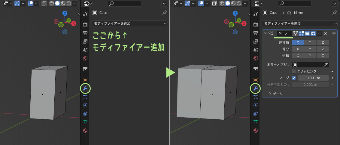
Now if you edit only the right side of the cube, the left side will automatically be created as a mirror.
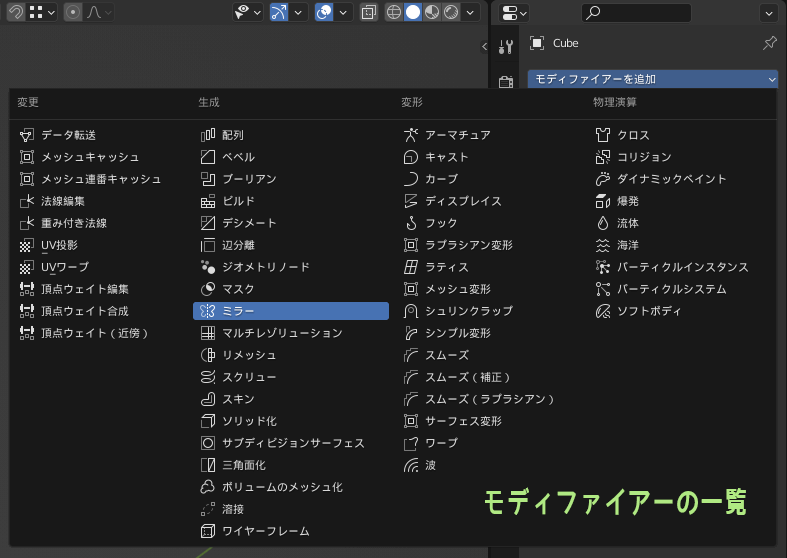
Starting with Blender 4.2, modifiers are no longer displayed in a list. You have to select a category such as Edit, Generate, etc., and then select each modifier.
*Click here for a list of modifiers that were previously displayed in Blender.
The Mirror Modifier has many settings. You can change or add the axis to be mirrored, and even turn off the mirror display in the 3D viewport.
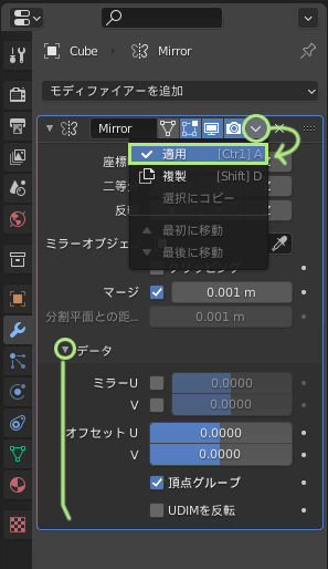
Modifiers can be removed or modified at any time unless you press the “Apply” button to apply them to the object. You can actually play around with the settings yourself to see what happens.
The Apply button is hidden in the folded menu.
If you open the Collapse menu in the data section, you will also see a setting to mirror UVs or not.
There is also a Clipping item in the mirror modifier settings.
If clipping is checked and turned on, vertices facing the mirror axis will be adsorbed to the axis, preventing vertices from inadvertently moving and opening a gap.

This is a very useful feature and I would like to actively use it.
(*The clipping feature is You told us in the comments! (Thanks for the info~)
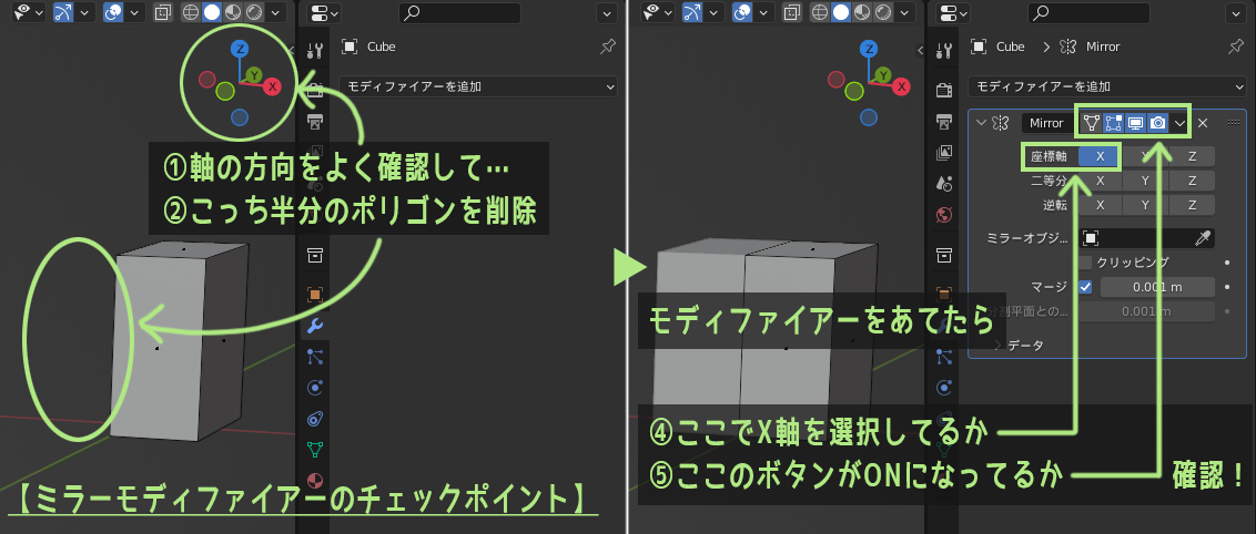
You’ve applied a mirror modifier, but for some reason, it doesn’t work! If this is the case, check the following 4 points!
- Is the axis properly oriented?
- Is that the right direction to remove polygons?
- At the modifier’s axis selection.
- At the modifier visibility button.
The problem of the mirror modifier not working is generally thought to be fixed by these four things.
– Save scene data
Once here, save the scene in Blender.
Scene data can be saved from the top menu
File->Save (Ctrl+S), or File->Save As (Shift+Ctrl+S).
It is better to save data frequently.
3DCG software, not just Blender, can freeze or crash unexpectedly. If you are working without saving data for a long time, you may lose all your work due to an unexpected freeze.
If you are concerned, you can use the Autosave feature.
Also, we recommend that you do not overwrite all of the data with a single data, but rather save each step as an alias and keep a version of the saved data.
Although it is very rare, it can happen that the saved data is corrupted by some problem and cannot be opened. If the data saved a short time ago remains, the damage can be minimized.
Actual modeling (2) Editing polygons and vertices in various ways

With the mirror modifier on top, we are ready for symmetrical modeling.
From this point on, polygon editing and vertex shifting are used to make the cube look like the body of the Toha model.
We will proceed by introducing tools often used in modeling and little tricks that are useful to know.
Incidentally, until I created the Toha model base shape from the cube, I used loop cuts and vertex moves to create it like this. (see figure below)
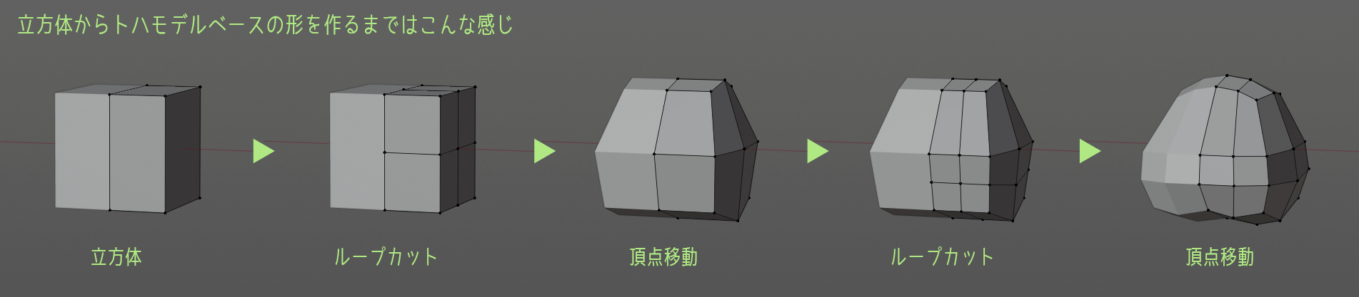
*For information on how to actually create the shape of a model from a cube object, see Character Modeling from Scratch! – How to Make 3D Models.
– Loop Selection
Vertex selection can be done from the toolbar box selection can be done from, but apart from that, loop selection is often used as well.
When using a Maya-like keymap, loop selection of vertices, edges, and faces can be done by double-clicking.
The trick is to double-click “around the edge in the direction you want to select the loop.
(*When using Blender keymap loop selection is Alt + click)
Selection systems can be made into additional selections by holding down Shift, so Shift and double clicking can be used for multiple loop selections.
– Convert selected vertices, edges, and faces to other elements
When a vertex, edge or polygon is selected in edit mode, if you switch directly to edit mode for another element, the selected portion will be converted to the element you are switching to.
For example, if you select an edge in edge edit mode and switch directly to Vertex Edit Mode, the vertices of the edge are automatically selected. The vertices of the edges are automatically selected.
Switching between elements can also be done with the shortcut 1 2 3 keys. It is good to use them together.
– Knife Tools
The knife tool can cut polygons more freely than the loop cut.
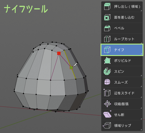
When you select the Knife tool from the Toolbar, the cursor shape of the cursor will change to a knife. Click once anywhere on the object and you will see green and red dots and lines.
If you move the mouse cursor as it is, points and lines move over the object.
The red-green point of the knife tool subtly snaps to the object’s vertices.
If you click on the red-green point when it snaps to a vertex, you can cut exactly at the vertex.
Clicking on an edge creates a new vertex at the clicked point.
At this point, holding down the Shift key and clicking will snap the red-green dot right in the middle of the edge. (If you are using an industry-compatible keymap, snap it by holding down the Ctrl key and clicking).
To confirm the cut, press Enter.
The knife tool allows you to click anywhere on the polygon to cut, even if it is not a vertex or edge, but if you cut too freely, you will end up with a lot of polygonal polygons.
Since nothing good can happen if polygonal polygons are left behind, it is recommended that additional cuts be made where polygonal polygons are left behind to make triangular or square polygons.
*For details, see separate article Human-friendly square polygons, game processing-friendly triangle polygons.

extension: Snap Utilities Line. When enabled, you can use Make Line, a tool much like the knife tool.
If the knife tool is not quite right for you, try the Make Line tool as well. For more information, please refer to Blender Modeling [Addendum].
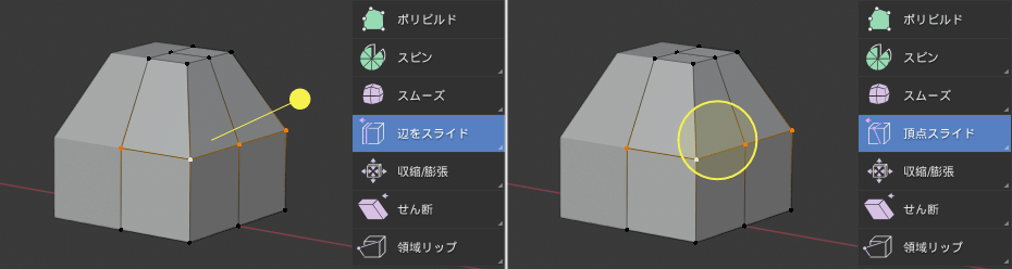
– Slide tool for edges and vertices
This tool allows you to slide selected edges or vertices along intersecting edges. To switch between tools, use the Toolbar You can do this by pressing and holding the “+” button.
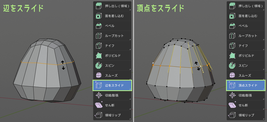
The shape of the displayed gizmo is different between the edge slide and the vertex slide.
It is very useful when you want to slightly change the position of a vertex or edge without changing the shape of the object as much as possible.
It is not often used in low-poly modeling, but when the number of polygon divisions gradually increases and the model becomes high-poly, it is useful to adjust the topology (polygon divisions).
– Shrink/Expand tool
This tool allows you to move selected vertices or faces in a bulging/squeezing direction.
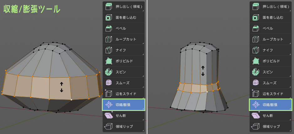
This means that you can move vertices and faces in their respective normal directions.
For example, you may want to make a character’s arms and legs thicker or thinner or create a larger clothing model from a copy of the body model.
In terms of the Toha model, it can be used to make the girth a bit thicker.
Mirror Modifier in use The clipping function can be turned on to shrink/expand in all directions, such as in the girth, without any problems.
Note that if the clipping function is turned off, the vertices facing the mirror axis will also move, causing the polygons to separate or overlap.
– Align vertices with scale
As you repeatedly cut polygons and move vertices, the position of the vertices will gradually become rattled.
At this point, let me introduce a small trick that allows the vertices to be aligned perfectly in one direction.
First, select the vertices you want to align tightly with Loop selection or box selection.
With that in place, switch to the scaling tool and move the gizmo grip in the direction of the axis you wish to align.
Press the zero 0 key on the keyboard as is. The selected vertices will then be aligned exactly.
– Merge vertices
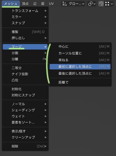
The merging of the selected vertices will be performed in the header, Edit Mode Menu You can do this from Mesh->Merge.
However, there is also a way to apply the scaling tool’s “Fit” function as described earlier.
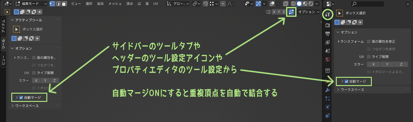
First, in the Sidebar, go to the tool’s Options and Auto Check the merge checkbox.
Tools setting icon in the header or You can also turn it on from the tools settings in the property editor.
If you turn on automatic merging, vertices in the same location will be merged automatically.
Once you have checked the box for automatic merging, select the vertices you wish to merge switch to the Switch to the Scale tool, and move the gizmo so that it can scale in all directions.
If you enter 0 directly from the keyboard, all selected vertices will be gathered into one point and merged.
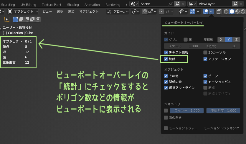
If you turn on [Statistics] in the viewport overlay and other information, such as polygon count, will be displayed.
– Sewing union of vertices
Automatic merging of duplicate vertices can be applied to join vertices as if they were sewn together.
To do a vertex stitch join, also used in conjunction with the snap feature. Turn on the snap function from the header menu and set the snap setting to “vertex”.
Grab the vertex to be stitched and move it to the vertex to be stitched to, and the two vertices will be snapped together and automatically joined.

Vertex stitching joins are also useful for adjusting polygon divisions (topology).
Once polygons can be cut, vertices can be moved, and vertices can be joined, most 3D models can be created. The next step in modeling is extrusion.
– Extrusion Tool
This tool can extrude selected faces and edges to create new polygons.
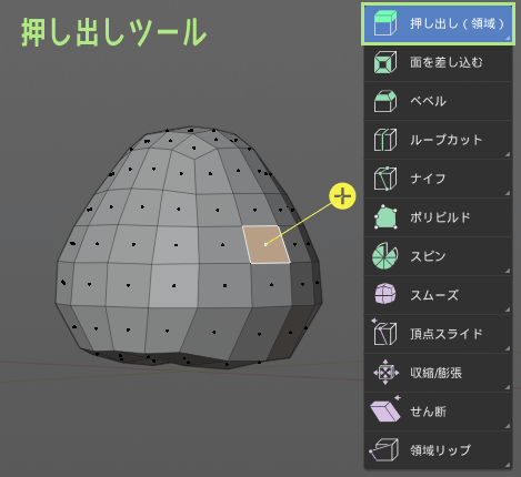
The extrusion tool is used very often in Toha-style polygon modeling.
In Maya’s extrusion tool, you had the option to choose whether the polygons were to be combined or separated after extrusion. Blender’s extrusion tools are divided into tools themselves for each option.
*To switch between tools, Toolbar You can do this by long pressing the button.
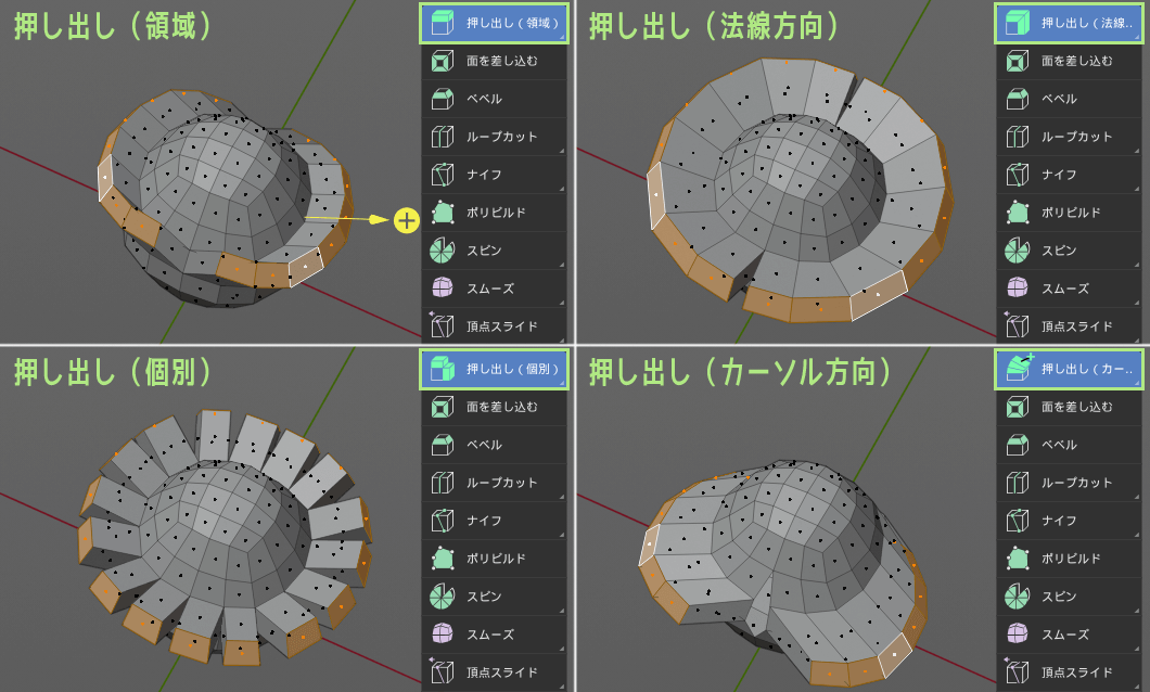
The “Extrude manifold” option provides a slightly special extrusion method when the surface to be extruded is flat.
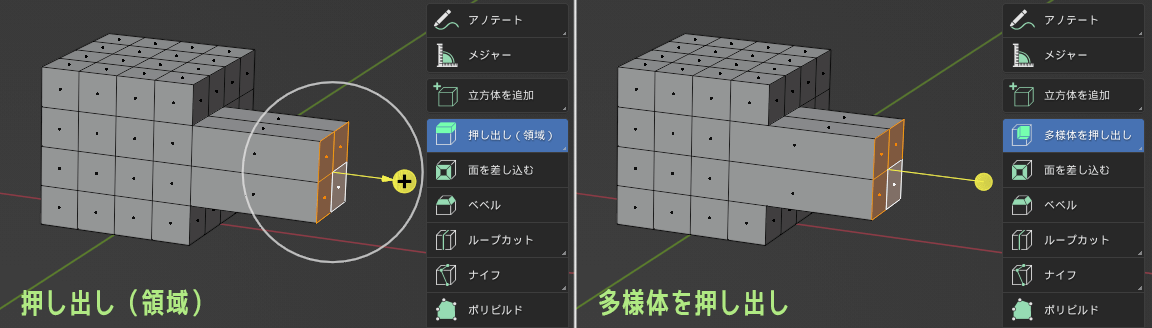
Note that the result after extrusion will vary depending on the extrusion tool selected.
Selecting the extrusion tool alone does not cause anything to happen; new polygons are created only when the surface is moved using the extrusion tool.
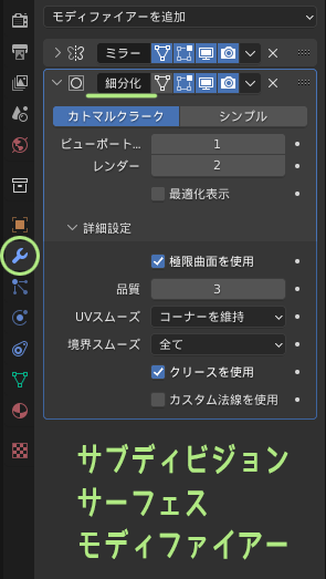
– Subdivision Surface Modifier
A modifier for subdivision surfaces (subdivision) is placed on a Toha model that has been extruded and feathered.
Add modifier in Property Editor -> Generate -> Select the subdivision surface.
*For information on how to add a modifier, please Mirror Modifier section.
With a subdivision surface, the polygon is automatically divided into polygons for high poly & smoothness.

The modifier is in a state of temporary effect until the “Apply” button is pressed.
With the Subdivision Surface Modifier, you can edit only the appearance to be high poly & smooth, without increasing the actual number of vertices.
Subdivision surfaces are often used to finalize the look, but they can also be used as a modeling technique in the process.
This method uses a subdivision surface to edit a smooth shape with fewer vertices, and once the shape is created, the modifier is “applied” and the topology of the details is adjusted manually.
I think this technique is quite useful for some low-poly 3D models.
– Modifier Order
Modifiers may give different results depending on the order in which they are placed on the object.
In the case of the Toha model, the mirror modifier was put on first. (1) Mirror (2) Sub-division surface The effects are ridden in the order of Property Editor the mirror is on top.
Blender hits the modifier effects in turn, starting with the modifier effect at the top.
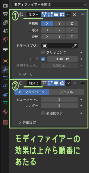
The order of modifiers can be swapped by grabbing and dragging the upper right corner.
I switched the order of the modifiers on the Toha model to test it out. (1) Sub-division surface (2) Mirror The appearance of the object will change.
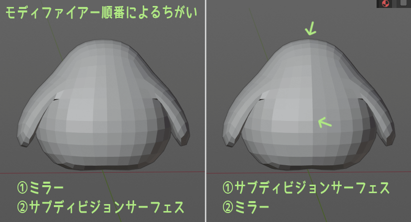
It is difficult to explain in detail how the order of modifiers affects the results since each modifier combination is different.
Anyway, it is good to remember that the modifier order has meaning.
Actual modeling (3) Fine tuning and Finishing

Once the modeling is gradually completed, we will edit the details of the model and finish the individual parts that have been completed.
From here, we will look at ways to make detailed work easier and what to do in the finishing stages.
– Selection Expand/Reduce
I made the feather part on the Toha model, and I will show you a small trick to select only the feather part.
Using Selection Expand/Reduce, you can successfully select intricate areas that are difficult to select with box selection, etc., can successfully select intricate areas that are difficult to select. In the header menu, select [Selection Use the “Zoom In/Out” option from the “Selection” menu.

Expand selection Shift+. , reduce selection Shift+,, but The shortcuts here The description changes depending on the keymap you are using.

Use loop selection together with selection expansion You can cleanly select only the wings like this.
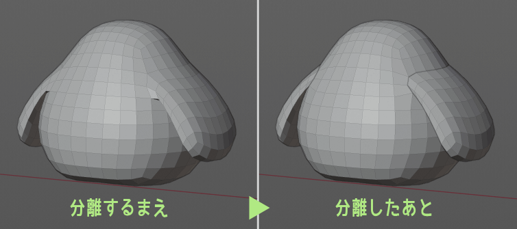
– Separation of Selected polygons
Try to separate the selected feathers from the body object to another object.
Edit mode menu [Mesh] on Header, then Separate->Select to do so.

Note that separating the body and wings slightly changes the way subdivision surfaces are applied.
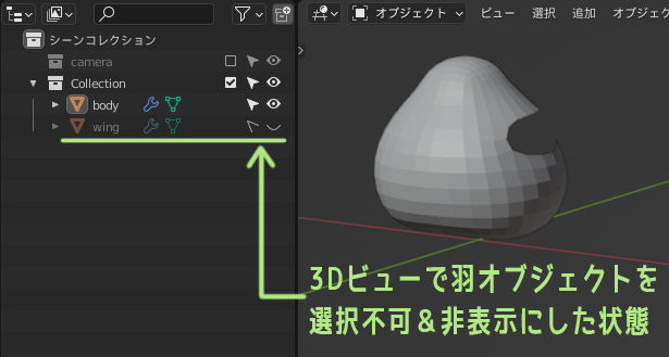
– Object Management with Outliner
Separating the feather and body objects out liners to manage each object, making modeling easier.
For example, when editing a body, you can hide wings if they are distracting, or lock wings so that they cannot be selected. The arrow symbol controls whether the feathers can be selected or not, and the eyeball symbol controls whether they can be shown or hidden.
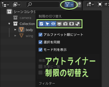
If you do not see the control icons in the outliner, you can display them by opening the Toggle Restrictions menu from the top right mark and turning on the respective icons.
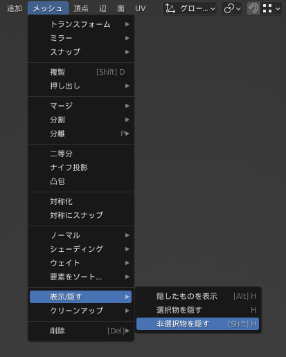
– Display only Selected polygons
There is also a way to show/hide polygons on a per-polygon basis instead of per-object basis.
Select the polygons you want to display, and Header to Edit Mode Menu from [Mesh], click on Show/Hide -> Hide non-selected items In the same place is, Hiding Choices so Show hidden items.
When editing the details of the 3D model, you can work without stress by hiding the distracting parts to make it easier to work with.
In addition, shift-move, rotate Zoom in/out, and focus on the selected area (Maya-style keymap while using the F key) make it easier to work with details.
– Flat shade/Smooth shade
Once the object has been modeled, the polygon smoothing process is set up as a finishing touch.
For more information on smoothing, see Polygons are planes, You can’t create a “curved surface” by collecting polygons.
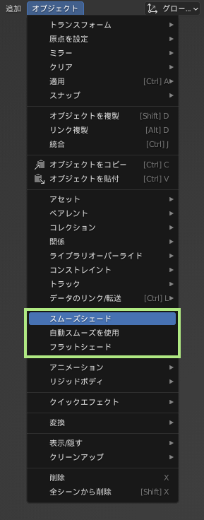
To apply the smoothing process, header in the From the Object Mode menu, select Object -> Smooth Shade. (Conversely, smooth shades can be removed by going to Object->Flat Shades).
However, simply using smooth shades may result in poor shading.
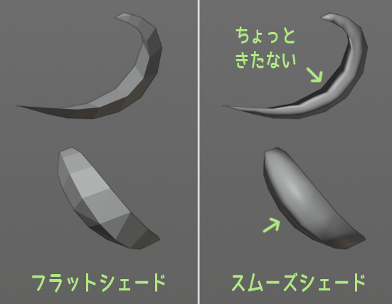
In such cases, there are two ways to adjust shading.
- Adjustment with “Smooth Shade” and “Mark Sharp”
- Adjustment by specifying angle after “Auto Smooth Shade”
1. Adjustment with “Smooth Shade” and “Mark Sharp”
To do Method 1, first select an object and smooth it by choosing “Smooth Shade” from the Object Mode menu.
Then, set the object you want to adjust the smooth to Once you are in Edit Edge Mode and select the edges you don’t want to smooth, Mark Edge→Sharpen on header menu.

This allows you to adjust the smoothing location to your liking.
2. Adjustment by specifying the angle after “Auto Smooth Shade”
If the adjustment can be made simply by specifying the angle at which the smoothing is to be applied, Method 2 can be used.
To do this, select an object and choose “Auto Smooth Shade” from the Object Mode menu to apply smoothing.

When automatic smooth shading is applied, “Smooth by Angle” is added to the modifier tab. Here you can adjust the angle at which the smooth is applied, ignore areas marked sharp, and so on.
The “Smooth by Angle” modifier is only displayed when automatic smooth shades are applied, and will not appear in the modifier tab when “smooth shades” or “flat shades” are applied.
– Object Cleanup
The final 3D model should be cleaned up or the data cleaned up by erasing unnecessary values during the work process.
Creating clean 3DCG data is a good thing. Please refer to another article for more information.

The cleanup is in the Header to Edit Mode Menu in [Mesh] -> Cleanup, You can clean up data.
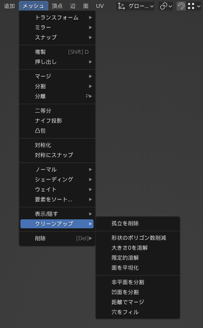
There are various options, but duplicate vertices can be merged using “Merge by Distance”. Remove Isolations” can be used to remove odd faces or vertices that are isolated.
– Apply objects (Freeze & Reset)
Also, to clean up the object’s movement and rotation values, apply the object.
It is common practice to set the position and rotation values to (0, 0, 0), the scale value to (1, 1, 1), and the position of the origin of the 3D model to the origin of the global coordinates.(*Unless there is a special specification in terms of specifications.)
To get to this state, go to the Header to object mode menu [Apply], and do a full transformation, which is the same as a freeze and reset in Maya.
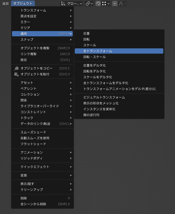
You can also apply only position, only rotation and scale, etc., depending on the situation.
Summary: When the model is completed, the modeling operation is approximately known

If you made it to the end of the post, thank you very much! Thanks for your hard work~!
This is a very long article, but I hope that this [Practical Edition] and a separate article [Knowledge section] cover the minimum requirements for modeling in Blender.
All you have to do now is to actually move your hands, so please refer to the article and try your hand at making various things.
You can also take the next step by reading Blender Modeling [Addendum]
As a next step, Blender’s UV expansion I also wrote an article about Blender’s UV expansion! It introduces some useful add-ons and features for manual UV expansion. Please take a look at it when you are done modeling and want to expand UVs.
I hope to write about armatures and materials in Blender at some point, but I don’t know when that will be.
As I am still learning Blender myself, I will write a new article when I have a better understanding of Blender to share with others.
Let’s live a 3DCG life with Blender, and let’s work hard for each other~!
Go Go!
Thinking of trying Blender? If you think so, please also read this Blender Getting Started Series.
*To ensure that the model data you worked so hard to create is not lost in an unforeseen accident. Computer Backup Please check back soon for more information!

- Coments - コメント一覧